
Panel Wiring Standards: Ferrules, Colours and Labels
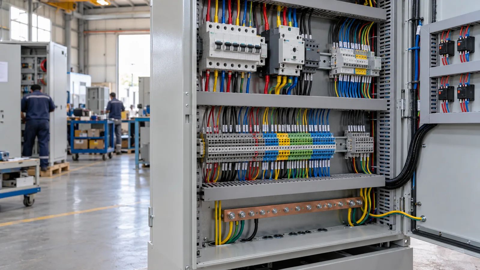
Panel wiring standards set the colour of each conductor, the way ends are terminated and how every wire is numbered. For machine control panels, IEC 60204-1 gives the colour rules: black for power, red for a.c. control, blue for d.c. control and green-yellow for earth. Ferrules on every stranded end and matching labels at both ends complete the practice.
What you receive: send your schematics and wiring requirements, and your quotation within one working day states the wiring standard, ferrule and label scheme and test steps. Request a quotation
By Eng. Babu Parkash, Panel Engineering, Saudi Control Panels Company. Published October 2026.
Which standard governs control panel wiring?
Three documents sit behind most panels.
- IEC 60204-1 covers the electrical equipment of machines. It sets conductor identification, cross-section guidance, routing and protective bonding.
- IEC 61439-1 and -2 cover low-voltage switchgear assemblies, including internal wiring, connections and verification.
- The project specification adds client rules, such as preferred colours, labelling language and approved cable types.
If they conflict, the project specification and the more demanding rule normally win, and the conflict should be resolved in writing before the build.
What colour is each conductor?
IEC 60204-1 gives a clear scheme for machine panels.
| Circuit | Colour | Note |
|---|---|---|
| Power, a.c. or d.c. | Black | Main circuits |
| Control, a.c. | Red | Contactor coils, relays |
| Control, d.c. | Blue | 24 V d.c. circuits |
| Interlock from an external source | Orange | Warns that the wire stays live when the panel is isolated |
| Neutral | Light blue | Where used |
| Protective earth | Green-yellow | Reserved for earth only |
Phase colours on power distribution boards follow a different convention. Projects in the Kingdom may specify the older red, yellow and blue, or the IEC brown, black and grey, so confirm which the project calls for before ordering cable. The answer should come from the specification, not from habit.
How should ends be terminated and numbered?
Treat every stranded end with a ferrule. A bare stranded end splays under a screw terminal, loses strands and loosens over time. An insulated bootlace ferrule, crimped with the right tool, gives a solid end that seats well.
The common colour code for insulated ferrules, based on DIN 46228, relates to cross-section:
| Cross-section | Ferrule colour |
|---|---|
| 0.5 mm² | White |
| 0.75 mm² | Grey |
| 1.0 mm² | Red |
| 1.5 mm² | Black |
| 2.5 mm² | Blue |
| 4 mm² | Grey |
| 6 mm² | Yellow |
Follow four practices for good terminations:
- Match the ferrule to the conductor. Select by cross-section and strip length.
- Crimp with a calibrated tool. Pull-test a sample each shift.
- One conductor per ferrule and per terminal, unless the terminal is rated for two.
- Tighten to the torque on the data sheet, and spot-check with a torque screwdriver.
Worked example: numbering one motor circuit
This is a worked example with invented numbers, to show the method. A schematic shows a motor starter with a start button, a stop button and a contactor coil. The wire-numbering rule is: each electrical node gets one number, and the same number appears at both ends of every wire on that node.
| Node on schematic | Wire number | From | To |
|---|---|---|---|
| 24 V d.c. supply, positive | 101 | Power supply +, terminal X1:1 | Stop button contact 1 |
| After stop button | 102 | Stop button contact 2 | Start button contact 1 |
| After start button | 103 | Start button contact 2 | Contactor coil A1 |
| Contactor coil, return | 100 | Contactor coil A2 | Power supply 0 V, terminal X1:2 |
A technician holding the schematic can find wire 102 at either end, and a fault finder at the panel can match each label to the drawing without tracing. The same rule gives every terminal a tag, for example X1:1, taken from the terminal plan. When two wires land on one terminal, both carry their own numbers.
Label by function too. Each device carries a tag, such as K1 for the contactor and S1 for the stop button, that matches the schematic, and a nameplate describing the load in plain words. The panel layout, the schematic and the labels should use one set of tags.
How are panel wiring standards verified?
By inspection and test. At the workshop, the wiring is checked against the schematic, terminals are torque-checked, and the protective circuit and insulation resistance are measured. The functional test then proves the wiring performs as drawn. Our in-house FAT follows IEC 61439 routine verification, and a customer or third-party witness is welcome. The sequence is shown on the panel FAT and testing page.
Our approach to wiring practice is set out on the control panel wiring services page, including the standard ferrule and label scheme, and the options for customer-specific rules. For PLC cabinets, the same discipline applies to I/O wiring, covered in PLC and automation panels. If you lack a clean set of drawings, panel design and drawings produces one with the wiring list and labels included.
Questions about panel wiring standards
What is a panel wiring diagram?
A panel wiring diagram shows how the devices inside a panel connect, usually as a schematic plus a wiring list or terminal plan. It carries wire numbers, terminal tags and device tags, so a technician can build, test and fault-find the panel from it.
What is the colour code for electrical wires in Saudi Arabia?
It depends on the project. Many specifications use IEC colours for phases, with green-yellow for earth and light blue for neutral, and some older installations use red, yellow and blue. For control wiring in machine panels, IEC 60204-1 applies. Confirm the colours in your specification.
Which colour is L and N in a wire?
In IEC colours, the line conductors are brown, black and grey, and the neutral is light blue. Earth is green-yellow. In older practice, line conductors were red, yellow and blue, so check which scheme your site uses before connecting.
Why use ferrules on panel wiring?
Ferrules keep stranded conductors together under the screw, so the connection stays tight and no strand escapes to touch a neighbouring terminal. They also speed up maintenance, because a ferruled wire can be removed and refitted many times without damage.
Can you wire to our own wiring standard?
Yes. Send your wiring specification with the drawings, and the quotation will state the colours, cross-sections, ferrule type and labelling to be used, so the build and the FAT check follow your rules, not ours.
Want a build that follows the panel wiring standards on your specification? Send your schematics and wiring rules, and we will confirm the scheme and the quotation within one working day.